
Problem:
Does anybody can provide a manual how to use Premium Tech Tool?
I’ve got a 2011 VN at the shop yesterday that is connecting to PTT 2.5.87 and PTT 2.4.87 as older electrical system. I run this tool (with PTT closed), enter the chassis ID, select VERSION2 and the tool showed me “Done” after some time. But once i’ve connected to the truck it still being showed as older system. I’ve tried to enter chassis ID as N****** and N ****** but with no luck. Both PTT seems working good as it was installed by trusted forum member and i have no problems with other trucks.
I’ve got a 2011 VN at the shop yesterday that is connecting to PTT 2.5.87 and PTT 2.4.87 as older electrical system. I run this tool (with PTT closed), enter the chassis ID, select VERSION2 and the tool showed me “Done” after some time. But once i’ve connected to the truck it still being showed as older system. I’ve tried to enter chassis ID as N****** and N ****** but with no luck. Both PTT seems working good as it was installed by trusted forum member and i have no problems with other trucks.
Solution:
Step 1, Open Volvo Tech Tool, system detected OLD ELECTRICAL SYSTEM, click finish job.
– FIRST clean/remove HISTORY on LATEST SELECTION . DONT CLOSE Tech Tool!.
– FIRST clean/remove HISTORY on LATEST SELECTION . DONT CLOSE Tech Tool!.
Step 2, Run OLD2V2 TOOL
-put chassis ID : full chassis number like this, example :YVAM390985Y036312
-select version 2 or version 3 (depend on your truck)
-hit button SET, Tech Tool will close automatic!.
-waiting until appear DONE. press it.
-put chassis ID : full chassis number like this, example :YVAM390985Y036312
-select version 2 or version 3 (depend on your truck)
-hit button SET, Tech Tool will close automatic!.
-waiting until appear DONE. press it.
Step 3, Open Tech Tool back, reconnect, still detect OLD ELECTRICAL SYSTEM, don’t panic
-DONT CLICK ANY SELECTION, just view and click FINISH JOB. Don’t close Tech Tool.
-PULL OUT THE DIAGNOSTIC CABLE FROM THE TRUCK’S SOCKET AT BELOW DRIVER SIDE, (NOT USB CABLE AT LAPTOP !!) and THEN RECONNECT IT BACK.
-DONT CLICK ANY SELECTION, just view and click FINISH JOB. Don’t close Tech Tool.
-PULL OUT THE DIAGNOSTIC CABLE FROM THE TRUCK’S SOCKET AT BELOW DRIVER SIDE, (NOT USB CABLE AT LAPTOP !!) and THEN RECONNECT IT BACK.
Step 4, Wait, Tech Tool automatically will detect/retrieve NEW CONNECTION and we can change to VERSION 2 or 3 on popup MANDATORY selection box,
DONE!
Reference: Volvo Tech Tool User Manual
About Tech Tool
Tech Tool is a tool that supports the repair and diagnostic process, developed in order to make the work in the workshops easier and more efficient. Tech Tool can be used online or offline (i.e. connected to central systems or not) in the workshop, out on the field, at the roadside or during test drives. Tech Tool is an application for diagnostic with possibility to use plug-ins to cover the whole repair process. With Tech Tool you can diagnose, test, calibrate and program a product. A product could be a vehicle, engine or a machine. Tech Tool also provide functions for updating the tool, and communication with the product and other external applications such as links to external websites or plug-ins. The set of plug-ins, user authorisations, and available languages is adjustable to provide every user with what they need.
Tech Tool menu
These menu options are available in the Tech Tool menu. Menu option Description Connect to Central Systems or Work Offline Depending on if you are working online or offline you are able to connect to or disconnect from central systems. Update Product Information Update the product information data. Administrate Software… Order different types of software. Electrical system dependent. Administrate Software New… Order different types of software. Electrical system dependent. Settings Change settings for product and network communication. See Configure Tech Tool for details. User Preferences Change language and unit settings. See User preferences for details. Print Label… Print engine labels for available chassis IDs. Print Print the displayed information. Log off Log off the current user. Exit Exit the application.
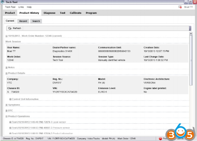
View product history
In Product History you will find the session logs. You can view the current session log or recent session logs for identified products. You can also search for session logs by date. In the logs you will find work that previously has been done on the selected product. It could be previously detected DTCs, product information and operations that have been performed.
Search
Under the tab Search you can search for old session logs by date.
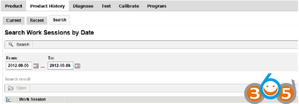
- Select the preferred time interval.
- Click Search.
If there are session logs within this time interval, they will be displayed in a list. You can perform the same actions with the session logs as in Recent session.
If you open an item in the search result, the item is opened as a closable tab (with date as the heading) to the right of the Search tab. It is possible to have a limited number of tabs opened at the same time.
View DTC information
With connection to product
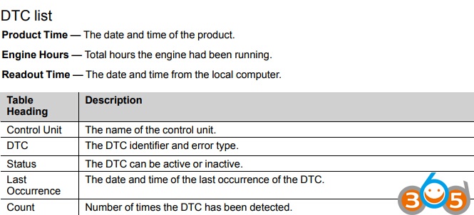
The DTC List displays the detected DTCs in the product. See DTC list for detailed information.
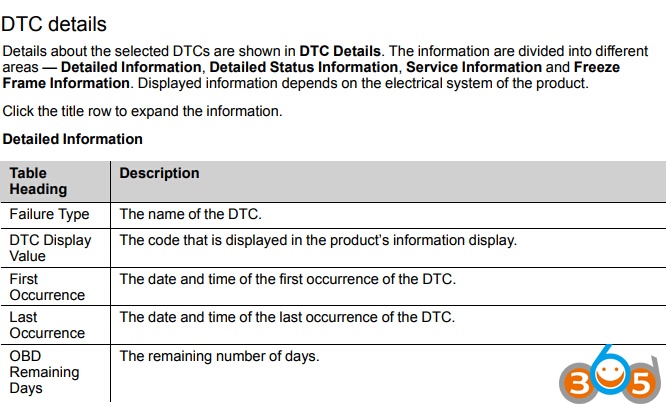
- Click Continue > . Information about the currently selected DTC are shown under DTC details.
Without connection to product
When there is no connection to a product, DTCs must be handled manually. 1. Click Edit List….
- Select DTCs by setting the status to Active or Inactive for the DTCs you want to add to the DTC list. See DTC list for detailed information,
- Click OK.
- Click Continue > .
Information about the currently selected DTC are shown under DTC details.

Run diagnostics
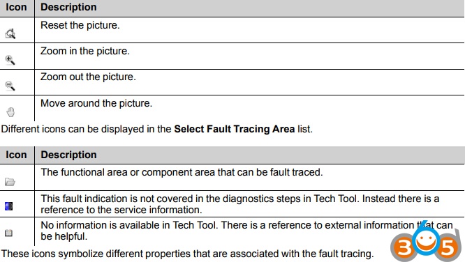
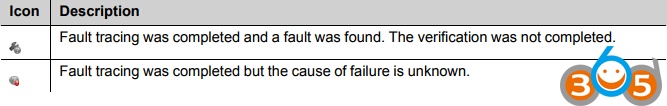
- Select a DTC area in Select Fault Tracing Area.
- Select one of the recommended procedures in Select Diagnostic Procedure. In some cases, you will be able to extend the list, see Extend list/Reduce list.
- Click Start > .
- Follow the displayed step by step instructions.

Test and calibrate
The operations that can be carried out depend on the product connected to Tech Tool and the level of authorisation of the user. Note that the screen images shown in the help text may differ from those in Tech Tool depending on the product that is being tested and the level of authorisation of the user.
The first time you select an operation which requires communication with control units after manual matching, the program reads information from the control units. This may take a minute or two. The program checks that the control units that store the chassis identity and serial number all contain the same chassis identity and serial number.
If the control units which store the chassis ID/Serial no. contain different chassis IDs/Serial numbers, no programming operations except MID XXX Control unit, programming can be carried out (XXX=MIDnumber).
Note: Test and calibration operations should not be performed on control units that have different chassis-ID/manufacturing.no, since there is a risk that the result of the operation could be incorrect or that the function is negatively affected.
Run a test or calibration
In Test and Calibrate you can select operations to test or calibrate a product.
- Select an operation by clicking on it.
Note: The functions can be sorted either as functions or function groups.
- To run the operation in simulation mode, select Run as simulation.
- Click Start to start the operation.
- Follow the displayed step by step instructions
Test and calibrate, VERSION 3 and 4
This section describes the functions available when an operation has been opened. Operation steps These steps follows the normal workflow when running a test or calibration operation.
Navigate through the steps in the operation by clicking Continue >. If you want to return to the previous step click < Back The description of icons that is shown during the steps can be found in the section Run diagnostics
Note: Since all operations are different, the steps may vary between the operations.
Information
This step contains the purpose and description of the operation.
In some operations you must select a specific component, for example a control unit or the right or left axle, or a variant of the operation.
Conditions
This step describes the conditions that needs to be fulfilled before you can run the operation. The conditions could be automatically read from the product, otherwise you must manually fulfil and confirm the conditions.
Execution
This step executes the operation. Some operations starts automatically. Other operations you must run and control manually.
Result
This step presents the result of the operation when it is done. After the presentation you must select if the operations was successfully done or not.
Wiring schematics
The wiring schematics shown by clicking on a link in the text field are to be used as a functional description. The schematic shows the conditions that apply when the function is active.
Note: The wiring schematics are not to be used as a basis for circuit measurements.
Cable colours
There are four colours – red, blue, green and black used on the wiring schematics
- Red is only used for power supply, irrespective of whether it is battery voltage or a supply from a control unit, for example 5 V.
- Blue, used for wires connected to a grounding point even if they are indirectly connected, i.e. via a control unit.
- Green is used for signal cables, primarily to indicate the signal cable from a sensor.
- Black is used where the function of the cable is not relevant or where the cable cannot be categorized according to the other colours.